Customization
Sayfield International
TKC ToolKit Creator
ADAMS/View Power-User Functionality
This section contains a text-based explanation and illustration of our in-house developed ADAMS based software called TKC (short for ToolKit Creator). The basics will be explained as well as the advantages of users of TKC in ADAMS. As a picture says more than a 1000 words, much of the functionality of TKC is also illustrated using YouTube videos. Please feel free to use and embed these videos, as long as you refer to Sayfield International.
Tutorials and screen recordings of TKC are placed on the Software tab.
If you are interested to make component-based, parameterized ADAMS models for your daily work, please contact us and we'll discuss the possibilities of bringing TKC as an ADAMS plugin to you or supporting you in other ways in making more efficient ADAMS/View based models.
We are convinced that, by using TKC in ADAMS/View to support the use of submodels and model components, you will make better quality and better documented ADAMS models in less time.
Check a selection of TKC based ADAMS animations and examples provided on our YouTube Channel (or search for TKC and ADAMS).
Short description of the TKC ADAMS Toolkit Creator Toolbox
The main purpose of TKC is to provide a generic environment to allow ADAMS/View users to rapidly define dedicated component toolkits with minimal overhead in defining user interface elements. TKC is a layer of ADAMS macros allowing users to define and create dedicated ADAMS toolboxes in a matter of hours. TKC allows the creation of small vertical applications, but also of larger toolkits with more complex interactions between components.
At Sayfield we typically create a new toolbox with dedicated components in a matter of minutes to prepare for a demo presentation.
Features of ADAMS toolkits defined in TKC:
- A TKC toolkit typically contains Component Objects, Data Objects, Sub-Components, Utilities, and Assemblies. All toolkit objects are stored in text files in ADAMS/View macro language in a single toolkit directory.
- For components, one can think of solar panels, car suspensions, pulleys or cable elements. Each component type typically has a unique model data object to define its parameters.
- Utilities are typically defined for conversion, model setup or I/O activities required in the toolkit. Utilities are identical to ADAMS macros, with the exception that TKC supports automated dynamic reloading of Utilities to drastically speed-up macro development and debugging.
- Sub-components are the smaller building blocks to define or extend the functionality of a Component. A typical Sub-Component is a parametric marker, part or constraint defined in a Component to extend its base functionality.
- Assemblies in TKC are typically models of complete products or test situations. Typical assemblies are a complete ship including all cable systems onboard or a complete solar array system including deployment springs and synchronization cables.
- As all dialogs are generic, TKC has a minimal set of user interface dialogs. Only some 10 dialogs provide the core interface of all toolboxes. This vastly reduces the overhead in the development of new user-toolkits.
Main features of TKC based ADAMS models:
- TKC Models are actually 100 % compatible with plain ADAMS. No additional macros or binary code is required to simulate or modify a TKC based model. This means that TKC can be used as a pre-processor for ADAMS/View based models.
- TKC models typically are a combination of component objects and component data variables. Multiple components can refer to one data object, they can be nested and extended to support version control and minimization of code re-writing. TKC components are comparable to ADAMS/Car Templates, a component plus a data object is comparable to an ADAMS/Car Sub-Assembly.
- The generic TKC data modify dialog also allows for reading and storing design variable objects into and from Data Libraries. These Data Libraries can be defined in several levels and locations (reserved locations are: User, Site, Shared and Safe).
- Complete models can be stored automatically and reloaded from TKC Assembly files. Assembly files contain a list of components and data creation lines and typically consist of a few pages of readable and documented ADAMS/View code to allow further coding if necessary. An assembly file can be extracted automatically from a hand made ADAMS TKC model, and can be loaded using the generic TKC Assembly Loader.
TKC base functionality vs TKC toolkits
When using TKC inside ADAMS there are actually two levels of usage:
- The first level is the TKC backbone or base functionality. In this environment, all TKC macros are already available to the ADAMS user. The purpose of this environment is to facilitate the standard work of ADAMS users by providing a set of shortcuts (or macros) for often-used functionality. The main visible differences between a normal ADAMS session and a TKC ADAMS session are an additional TKC Pull Down Menu on the ADAMS Main Menu and some enhancements to the ADAMS Standard Toolbar.
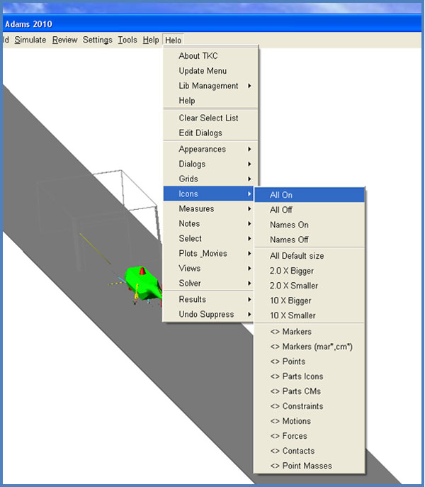
The TKC Pull Down Menu, as shown above, has a user-defined Project Label and contains additional selection buttons and pull-down menus with macro shortcuts.
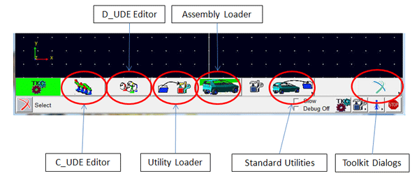
The TKC Standard Toolbar contains additional buttons, fields and selection lists to manage existing TKC based model objects or open TKC Utility and Assembly dialogs. Currently loaded TKC toolkits can be accessed from the Toolkits Dialogs button stack.
- In the second functionality level of TKC, all toolkits are managed and defined. Once components or data objects are defined in a model, you can use TKC modification dialogs to view, access, manage, modify and store/restore data objects. The animation below illustrates a typical interactive TKC object creation and modification session.
Modification of a TKC based MSC ADAMS Conveyor Belt model |
No further explanation will be included in this section of the core functionality of TKC. This will be made available to you as a user manual on your request. Instead, we will give a description of some of the most important groups of Toolkits defined in TKC
Cable Modeling Toolkits
A number of toolkits are defined in TKC to model Cable systems in several levels of detail. The basic idea here is that models of cables are as versatile in application and dynamics challenges as models of handling tires.
ADAMS TKC based CBL Cable model showing a hunting mode vibration |
- Axial only behavior: In some applications one cannot afford to model all cables in full detail. A typical example is the overall dynamics model of all cable systems on a large ship. The sheer amount of model elements would lead to excessive calculation times and memory usage. On the other hand, in typical cases the required output is mainly an overall dynamics response of the axial cable forces in the system in transient state.
- Axial and lateral behavior: In the next level, users may be interested in the dynamics of a cable system while undergoing force variations that are also related to lateral cable dynamics. Also, loss of contact between pulleys and cables my be a situation that is not likely to occur. In many occurring cases, this still doesn't mean that complete discrete cable elements must be used. In these cases, a simplified and drastically faster model method approach can be used. The method implemented in TKC combines zero-slip tangential pulley-cable contact with variable length cable sections containing a string of point masses.
- Contact based Pulley-Cable interface: In an even more complex simulation case, the interface between cables and pulleys requires a minimal set of pre-assumptions. We can think of a cable-pulley model where the contact between the cable and the pulley is intermittent or when the cable slips laterally on the pulley. Another dynamics situation that is hard (but not always impossible) to handle with simplified cable models is a system where an object is moving along a cable while passing several pulleys. In this aspect, one can think of a cable or ropeway system. Even in ADAMS, this kind of dynamics problem typically asks for a discrete cable connected to a series of Pulleys
Model of Solar Array deployment using the CBL toolkit of TKC |
Because of these considerations with respect to required model detail, three types of cables are defined in TKC:
- Tangent Cables
The CBL toolkit contains massless cables attached tangentially to pulley disks and other cable elements without slip. Rotation of the pulley and winch elements contributes to the extension and contraction of the force-based cable elements. Dedicated slipping elements are defined to model slip over pulleys using the Eytelwein formula.
Tangent type Cable system with Eytelwein based Friction |
- MidPoint Cables
Additionally, the CBL toolkit contains Midpoint based cable segments. Midpoint cable segments have an identical interface as the tangent cable segments and can be connected to the same pulley elements. As a result, model assemblies can be defined where all cables can be swapped from tangent to midpoint cables by changing a single assembly parameter and rebuilding the model.
CBL Midpoint Cable model to analyze Cable Snap Loads in an Offshore Application |
- Discrete Cables
The third level of cable modeling in TKC is based on a discrete element method. The level of detail is higher, and thus more geometrical parameters are required for a discrete cable than for the above-mentioned cable types. For discrete cables, the interface method between cables and their respective pulleys is based on contacts. Therefore for discrete cables a separate toolkit was defined labeled as CBT (for Cables, Belts and Tracks toolkit).
ADAMS Model of a Belt on Tapered Drums to analyze lateral Belt Stability |
The animation above illustrates the stabilization of a belt with a finite width over tapered cylindrical drums. Comparing results with a zero belt width model confirmed that stabilization requires a non-zero width of the belt.
Transport System Toolkits
Transport is not limited to one domain. It deals with land transport (two-wheeled, four-wheeled, tracked), water transport (vessels on or in the water) as well as air transport (aircraft, kites, etc.). For simulation tasks in transport-related applications, a range of TKC toolkits is defined. We will show a sample of applications to illustrate simulation possibilities and give a taste of our past experience in modeling and capturing dynamics system components into building blocks for complex system-level models.
- Two-wheeled Land Transport For the purpose of simulating a new bicycle-based concept a two-wheeler TKC toolkit was developed. The dynamic tire behavior modeled is incorporated from the TAR toolkit (Tires and Roads). The movies show some examples of typical fully parametric bicycle models defined.
MSC ADAMS defined bicycle modeling toolkit using TKC |
- Passenger car type Land Transport With TKC we have no ambition to compete with the ADAMS/Car vertical application. On the other hand, adding complex objects to an existing ADAMS/Car model is a viable need. The animation illustrates how the TKC environment can be used inside the ADAMS/Car program. Management of the TKC model data parallel to the ADAMS/Car model data is solved in an intuitive way.
Sample of TKC used inside the MSC ADAMS/Car vertical application |
Besides the possibility of embedding TKC in ADAMS/Car, it has also been used to model complete vehicles. This was done, mainly as a feasibility test as cars tend to have complex axle components with numerous variations. The main challenge here was to conceive a method for defining a flexible range of vehicle suspension types while not cluttering the Toolkit repository by having to store code for all these types. The solution was found by defining a set of Axle Sub-Components such as Springs, Rollbars and wheel hub Uprights. These sub-components can be incorporated in an existing Axle model component to complete the desired axle topology. No additional Toolkit code is required as the interface and parameters of the axle sub-components is stored in the data object for the axle instance itself. The sub-component concept also gives more flexibility in modifying or even upgrading existing components. As a result, the sub-component concept is used more and more in recently developed TKC toolkits.
- Water-based Transport Historically seen, the Netherlands has been a world-leading country with respect to offshore activities. We notice that partners from this industry are increasingly interested in using Computer-Aided Engineering to face new Engineering challenges. Due to the nature of the onboard dynamics, Multi-Body simulations are proving to be a useful method to address these issues. Typical maneuvers in the offshore industry are related to large motions at relatively low frequencies combined with unpredictable environmental conditions such as waves and wind. The main challenge for water-based systems is in the description of the motion of vessels due to the hydrodynamic forces.
In short, the dynamics of floating objects can be divided in:- A stiffness term (or position related force/moment) caused by upward forces on the wetted volume of the Hull. In the TKC HYDRO toolkit, a method is implemented to solve this issue for an arbitrary shaped Hull. The method uses a number of lookup tables, accounting for the change in wetted volume of the Hull while undergoing large motions and orientation changes. The lookup tables are generated in an off-line ADAMS/View session that has to be performed only once for each Hull geometry Thus, the non-linear stiffness matrix of a ship in the water is updated using an extremely time-efficient method.
Buoyancy effect on a Simple Hull shaped ship submerged in Water
- A damping term (or velocity related force/moment) caused by the drag of the Hull wrt. the fluid and by the effect of wave dynamics. The complexity of Hydrodynamics is due to the need to accurately solve drag forces while the Hull undergoes large displacements and orientation changes. In many Hydrodynamics codes, these changes are not updated during a simulation. This means that, for a cases where ships undergo large displacements, different simulation runs have to be submitted to account for re-calculation of the drag coupling matrices. At this point, Sayfield is working with a number of partners and clients in a consortium to generate code or interfaces with which ADAMS models can benefit from existing codes or methods to accurately describe hydrodynamic effects. If you are interested to use this kind of functionality in ADAMS, or want to learn more about the consortium mentioned, please contact us for further information.
- An additional mass (acceleration related) effect due to the fluid pushed aside by motion of the Hull geometry. Added mass is an effect that often cannot be neglected while analyzing dynamics of floating objects. Moreover, both the added mass as well as the drag effect on a moving vessel depends both on the current orientation as well as on the frequency with which the vessel is moving.
TKC based MSC ADAMS model of a large vessel for lifting and moving Oil Rigs
The above animation shows an example of a simulation of the hoisting of an oil rig at sea. The hoisting ship is currently been engineered by a large Dutch offshore company.
General Machinery Toolkits
As the title already indicates, General Machinery contains a wide range of different application fields. In these fields, a number of mechanical building elements keep re-occurring. Dynamic models of a number of these building elements are captured in a range of TKC toolkits. Several of these toolkits have already been used and verified in a number of consultancy projects. In this section, we will show a number of ADAMS simulations created with TKC. Please contact us if you want to know more about any of the toolboxes used.
- Conveying systems
A first conveyor belt example shows a model of a discrete belt modeled as rigid segments with additional geometry on each segment. In TKC, all geometries in a component can be tagged for use in contact connections to other components. As a result, users can make a complex component-to-component contact, possibly introducing hundreds of separate contacts, with a single command. For conveyor systems, this approach ensures that all conveyor segments make contact with geometries of a range of transported objects.
ADAMS TKC based model of a Paper Conveyor |
A second conveyor type model illustrates the use of a number of new components in CBO, a dedicated toolkit for transporting Cardboard Box-shaped Objects. This toolkit has been defined in a consultancy project and illustrates the advantages of using Multi-Body simulations in prototyping transport systems for products with complex and varying system conditions.
Simulation Results of a Stack of 20 Boxes on a Conveyor belt |
A number of CBO components are described to illustrate the typical system-level approach used in TKC toolkits to allow running a range of different simulations. The figure below shows an overview of the CBO toolkit functionality.
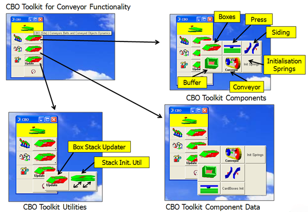
Basic components defined in the CBO toolkit are:
- Conveyor Model: a zero degrees of freedom belt from the CBT toolkit. By pre-definition of geometry and constraints, a minimal representation of a conveyor belt has been defined. The obtained conveyor belt model is capable of running practically in real-time.
- Stack of Boxes: a component defining a range of boxes. The number of boxes is a user input parameter. The boxes are aligned with respect to a Reference marker in space and have a parameterized relative spacing and orientation. A major challenge in creating the CBO toolkit was the presence of a vast amount of contacts between cardboard boxes and between the boxes and the surrounding objects. Also, due to the thin cardboard material, correct contact simulations of a stack of boxes required a dedicated model approach.
- Box Stack Buffer: a component defined to contain a stack of boxes. It consists of solid walls that can be in contact with the sides of the boxes and a shutter plate to start a transfer of stacks of boxes.
- Bearing systems
Bearings are one of the most used components in the mechanical industry. In creating a model for a bearing, similar questions will come up with respect to the modeling of cables and tires. The main decision factor for the bearing model to be used is the level of complexity required in the output signals. For a simple case, a revolute joint will be sufficient to model a bearing. On the other hand, bearing manufacturers have developed bearing models with over a thousand degrees of freedom that require hours of computer time to simulate one revolution.
MSC ADAMS TKC based model of a contact-based bearing with 7 Degrees of Freedom |
The TKC environment has been used to define bearing models at a reasonable pragmatic and simplified level. The framework of TKC, however, does not limit in any way expansion towards more complex bearings or using external codes connected to ADAMS. We have included an animation of one of the medium level bearing models defining 7 DOF to describe the relative motion of the parts for the balls and cages.
- Cams and Gears
In several recent consultancy project, models of cams and gears were required to transport motion through a mechanism. TKC now contains a gear toolkit including a tool to define the evolute shape of gear teeth contact. Option are available in the toolkit to vary between Planar gears, Three-dimensional contact-based gears and flexible gears based on discrete elements. An extension to include flexible bodies into the toolkit is considered for the near future.
MSC ADAMS model of a set of Solid Contact Planar Spur Gears |
Heavy Transport Toolkits
Several examples have already been included in this document to illustrate use of ADAMS in the area of heavy transport. One additional movie is included here to illustrate the possibility to define booms of cranes using input data from the FEM code STAAD. The model illustrated is automatically created from a STAAD input file and also illustrates the possibility in ADAMS to make complex
MSC ADAMS simulation of complex contact behavior in a heavy industry application |
Wind Turbine Toolkits
Sayfield has worked with several companies to investigate possibilities for an ADAMS based wind turbine toolkit. The model below demonstrates the possibilities of a TKC based wind turbine toolkit that we developed. The toolkit was considered a useful model environment in an evaluation project performed in 2004 by ECN and Vortech engineering. The animation shows a simple wind turbine model with a discrete flexible tower and a basic model of the gearbox and turbine blades. Definition and registration of the required components were done in a matter of hours, allowing the engineers to focus on component details and still keep an overview of the model topology.
MSC ADAMS model of a wind turbine including a 3D System View |